
Difficulty
Moderate
Steps
77
Time Required
01:00:00 - 02:00:00

User-Contributed Guide
This guide is not managed by the site's staff.
Quiz
0
-
-
I recommend not jumping in and pulling the entire printer apart at first like I did, mostly because doing so makes it very difficult to figure out where everything goes, and exponentially increases your chances of losing something important.
-
Doing this looks cool, and makes for some great snap streaks, but I’m pretty sure I have a couple screws loose because of it.
-
-
-
Make sure that your printer is turned off and doesn’t have any filament in it before you start disassembling it.
-
Don’t make my mistake the first time around and take it apart while it’s still plugged in
-
-
-
Please bear in mind that these were things I managed to snag on my way off campus as the quarantine went into effect, as well as a bunch of miscellaneous tools I found around my house, some of which I didn’t even know we had. Hopefully your toolkit will be more complete.
-
This is also just a visual re-tread of the tools section, so skip it if you already know what everything is
-
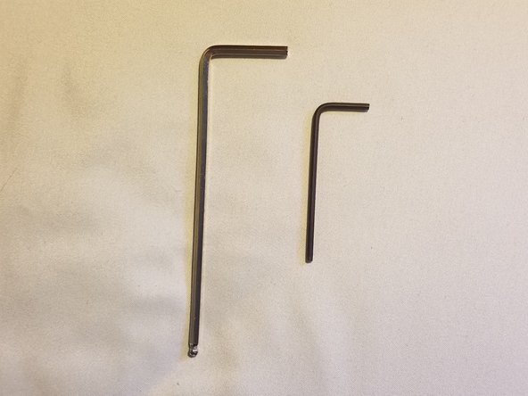
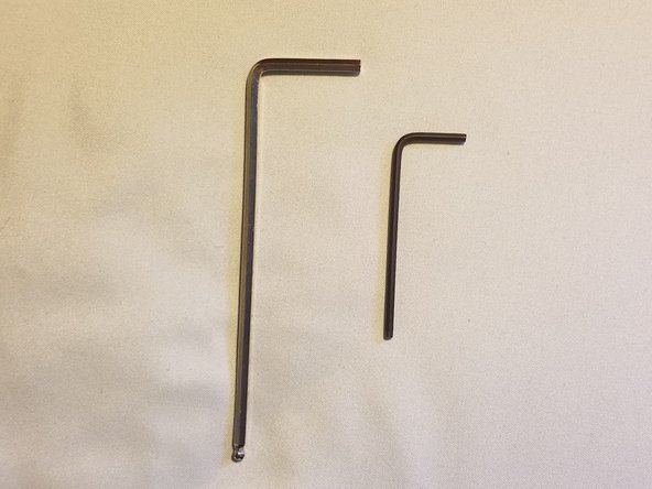
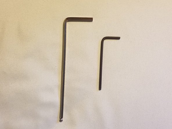
Hex keys in inch pattern
-
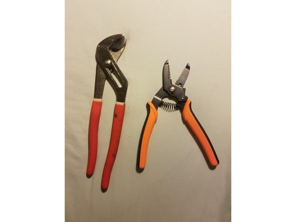
A wrench and wire stripper with gripping surfaces (A set of stamped steel wrenches would be better, but I didn’t one at the time)
-
Electrical Tape
-
-
-
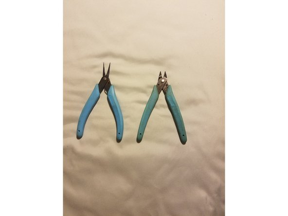
Pliers and flush cutters
-
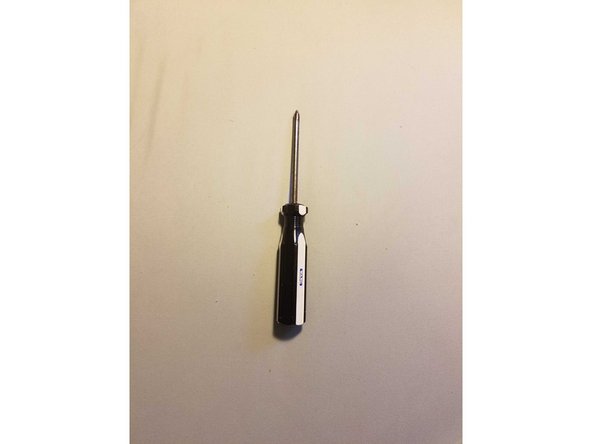
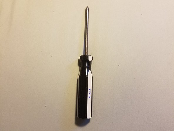
A large phillips head screwdriver
-
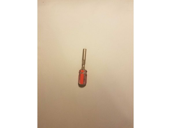
A screwdriver with a 6mm hex socket adaptor
-
-
-
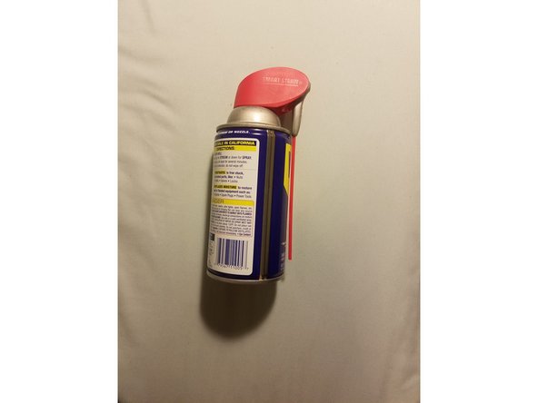
WD-40
-
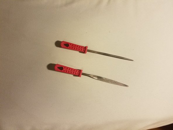
A set of hand files (you really shouldn’t need these, but I had to use them in one place. Even in that situation, a dremel would have been better)
-
-
-
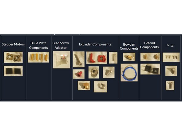
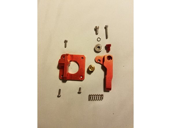
Here is a basic overview of everything the kit contains and will be elaborated upon in the upcoming steps
-
-
-
1x Extruder base and idler arm
-
1x Idler hinge Screw
-
1x Idler arm bearing
-
-
-
1x Filament bearing screw
-
1x Filament bearing shim
-
1x Filament bearing
-
-
-
1x Idler arm spring
-
1x Filament drive gear
-
-
-
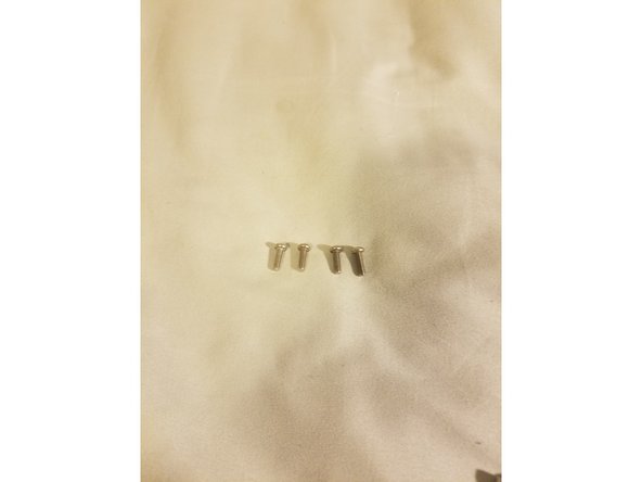
4x hex screws
-
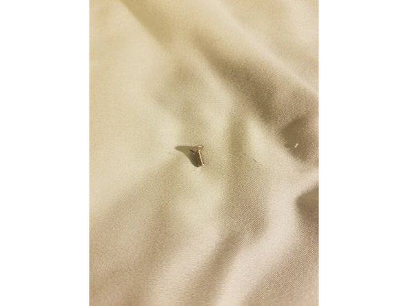
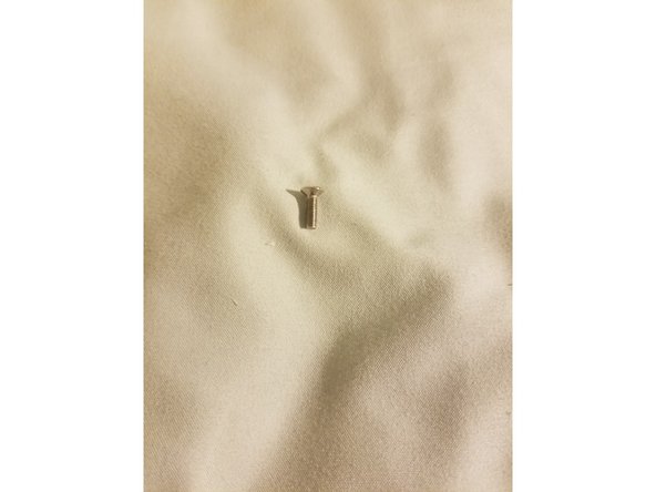
1x short countersunk screw
-
1x long countersunk screw
-
-
-
For this section you’ll need:
-
Two Allen keys from your set
-
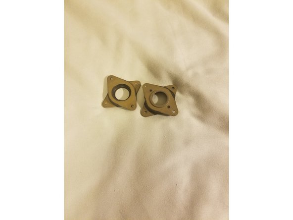
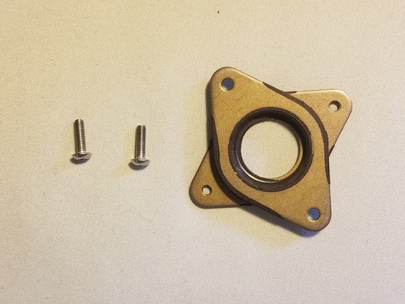
Two of the four rounded hex bolts and one motor damper
-
-
-
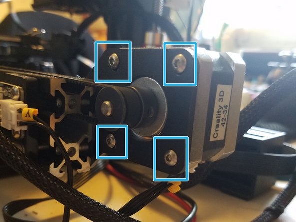
Warning: The motor is under tension from the belt, and might fly out of its bracket, off the table, and down a well if something doesn't hold it in place
-
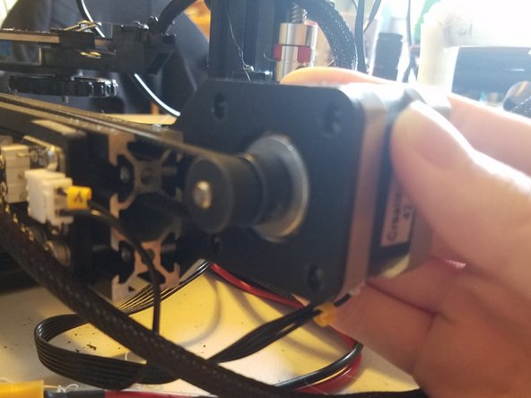
Undo the four hex bolts while using your hand to hold the motor in place.
-
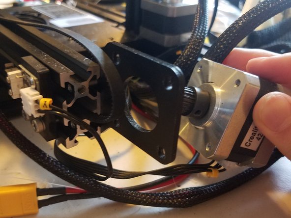
Gently tilt the motor housing backwards and out of its bracket, then disconnect its wire and put everything in a safe place
-
-
-
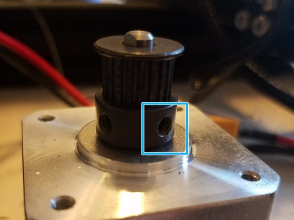
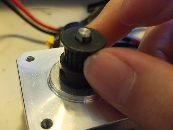
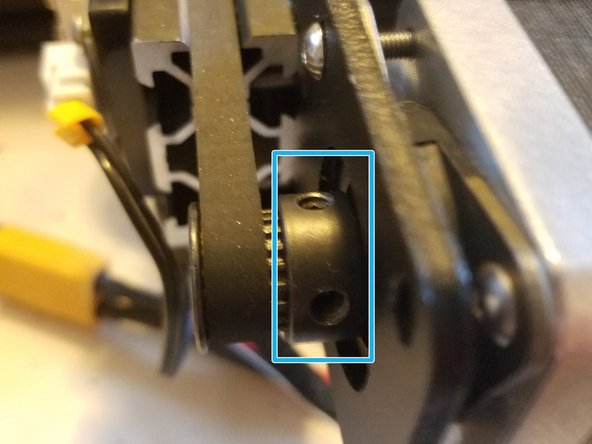
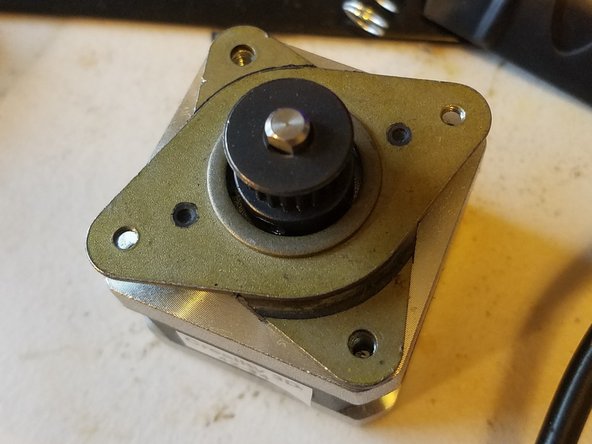
Loosen this grub screw on the stepper just enough so that the gear can be smoothly moved up and down by hand. There may be a second grub screw set at about 90 degrees from the first one, loosen that one too
-
-
-
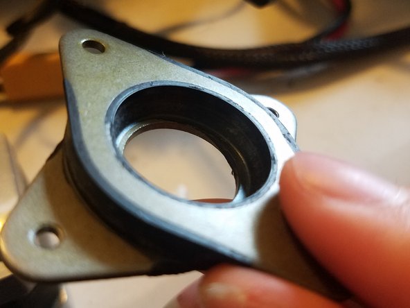
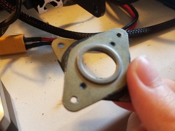
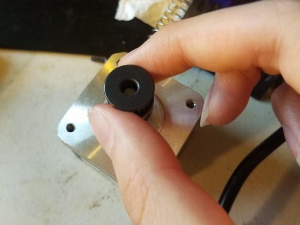
Place the sunken side of the damper onto the stepper motor so that the raised section on the other side faces upwards.
-
Fasten the two corners of the damper in contact with the motor with two of the screws originally used to hold the motor in place.
-
-
-
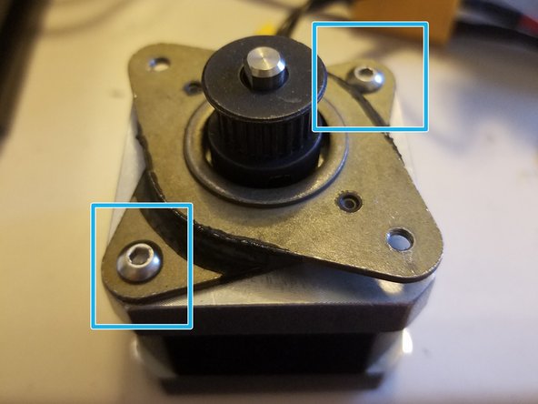
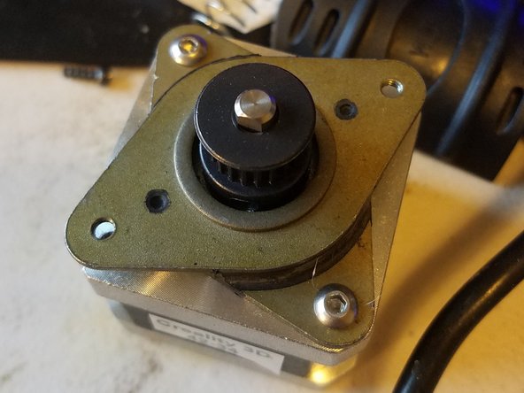
Place this new arrangement back into the bracket
-
Loop the belt over its gear, then tighten the motor and damper back into place using two of the screws from the upgrade kit
-
-
-
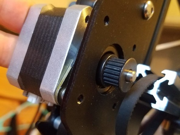
Push the build plate back and forth a couple of times to make sure the belt will run smoothly in the middle of the gear and won’t touch the bar it runs through.
-
If it doesn’t do this, move the gear along its axle until it does, then tighten it down so that all movements made by the stepper will also translate to the belt
-
-
-
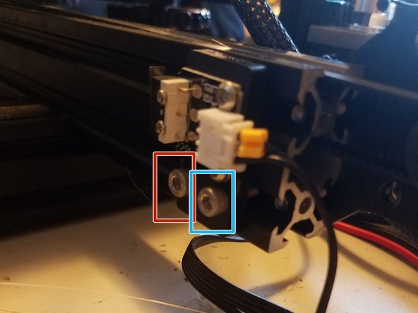
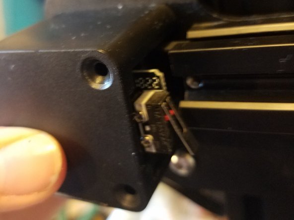
Undo the two screws holding the Y axis end stop in place
-
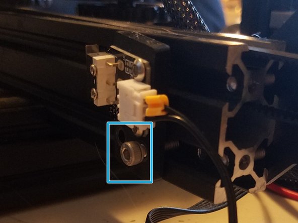
Move it forward so that screw B is in screw A’s spot. Make sure to tighten this enough so the endstop won’t rotate when the build plate hits it.
-
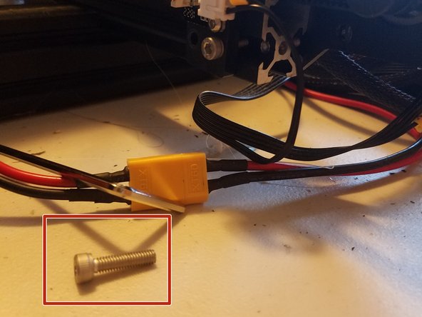
You will end up with an extra screw that I recommend you keep in a safe place in case you want to undo the process (This step sacrifices a couple millimeters’ worth of print volume in order to give the motor space)
-
-
-
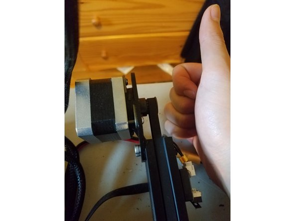
With that last step, you’ve finished installing the motor damper on the Y axis!
-
-
-
For this section you’ll need:
-
The same two Allen keys from your set
-
The other motor Damper
-
-
-
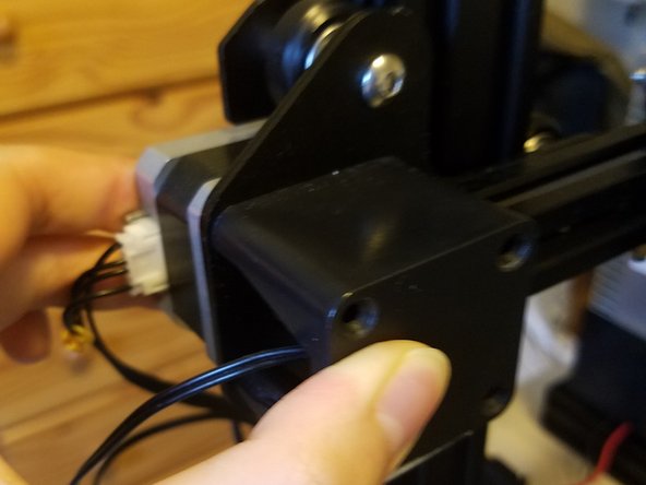
Warning: This motor is also under belt tension, as well as potentially being significantly higher off the table than the Y axis motor
-
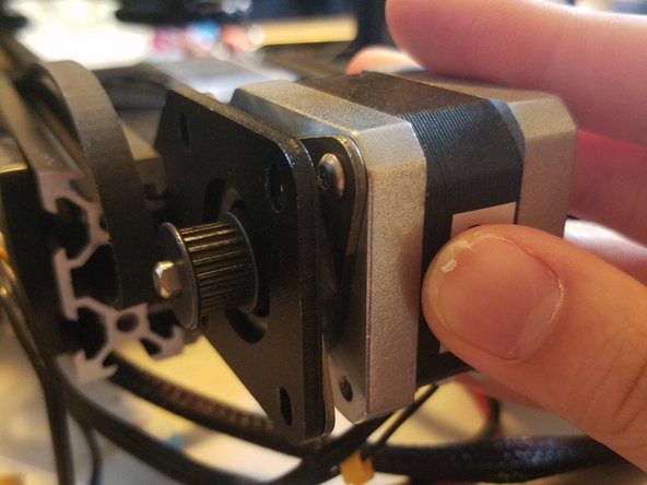
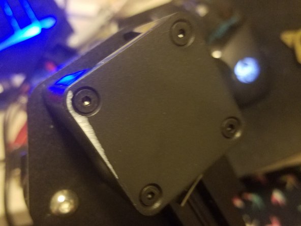
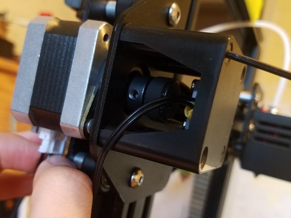
Remove the four screws holding the motor in, making sure to hold both it and the black cover in place while doing so.
-
Once all four screws are gone, you can let the cover dangle by its wire and just make sure the motor doesn’t drop out of its spot
-
-
-
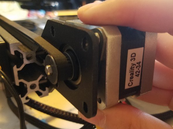
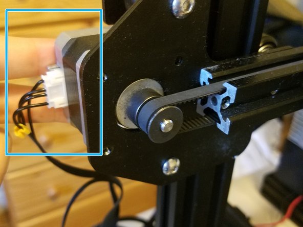
Repeat the process with the other stepper motor
-
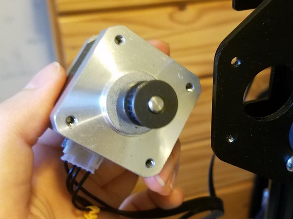
Pull it out of its bracket, this time disconnecting it from the printer so you can set it down on the table.
-
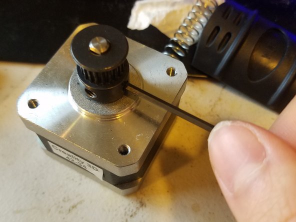
Loosen the grub screws on the gear just enough so that it travels up and down freely
-
-
-
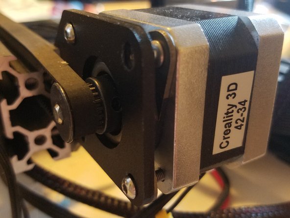
Hold the motor and the black cover steady, with the end stop facing inwards towards the nozzle carriage.
-
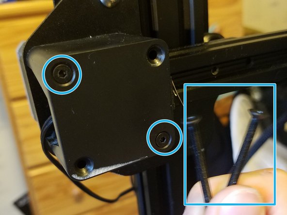
Tighten two of the original screws into the corresponding corners of the dampers, then reconnect the motor.
-
You'll have two extra long screws that you should put away.
-
-
-
With that done, you’ve officially completed the first step of the upgrade process!
-
Ok enough celebration, there’s still work to be done
-
-
-
There’s an A section and a B section in this part of the guide.
-
The A section pertains to Ender 3s with print beds that can be easily removed from the underlying metal plate via binder clips or something
-
The B section pertains to ender 3s with print beds that have some component that is glued to the underlying metal plate
-
This section took me about 4 minutes
-
-
-
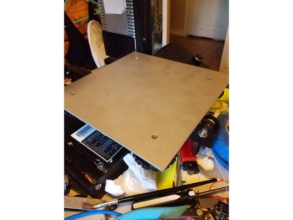
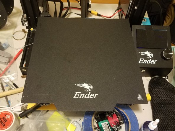
THIS IS SECTION A
-
Start by removing the print bed on top of the metal panel
-
For me this meant pulling the four binder clips off of the corners and then removing the whole thing
-
-
-
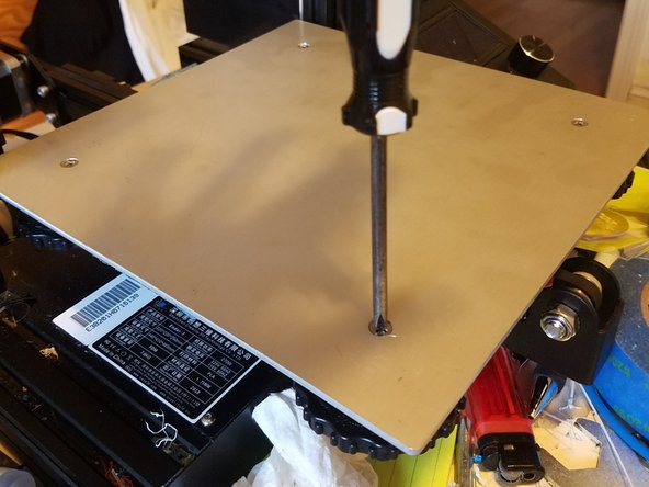
THIS IS SECTION A
-
Use the screwdriver to hold the screw in place while you undo the level adjustment wheel so that it comes off of the printer entirely.
-
Once it’s off, you can simply push on the screw from below and remove it from the printer.
-
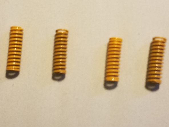
At this point, the spring will also be loose, so make sure you store that away as well, even though it won’t be needed from now on.
-
-
-
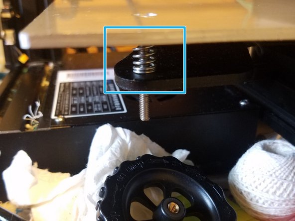
THIS IS SECTION A
-
Be Careful while removing the Build Plate.
-
The plate spring for the far left corner will be held within the same bracket that holds the wiring for the thermistor and heater cartridge.
-
-
-
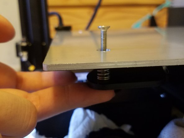
THIS IS SECTION A
-
Reverse the steps that you took to remove the build plate
-
Place each spring between the build plate and the metal gantry, then snake a screw through all three and thread it in place with the tuning wheel.
-
Take care when finessing a spring into the bracket holding the thermistor and heater cartridge wires.
-
-
-
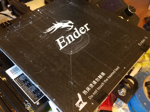
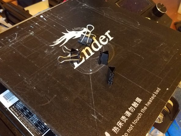
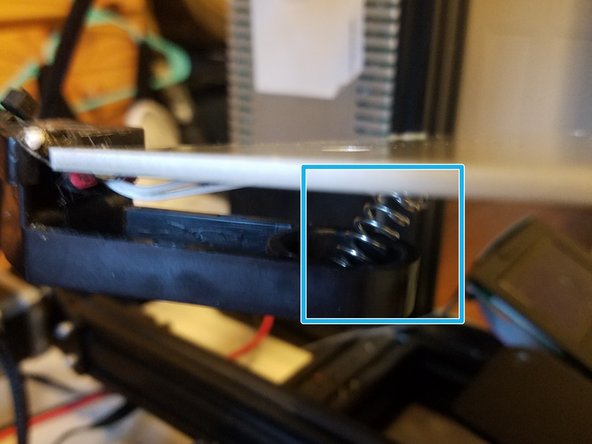
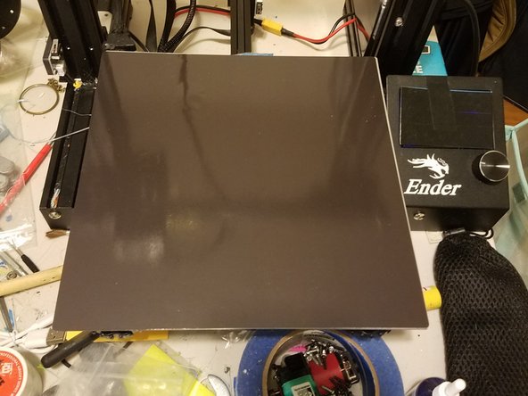
THIS IS SECTION B
-
If you have a print bed with a component that’s glued on like this new magnetic print bed, you won’t be able to access the screws without either damaging the bed, or the adhesive.
-
So instead of stabbing a screwdriver through the bed, just press down on each corner to relieve spring tension, then undo the corresponding adjustment knob
-
-
-
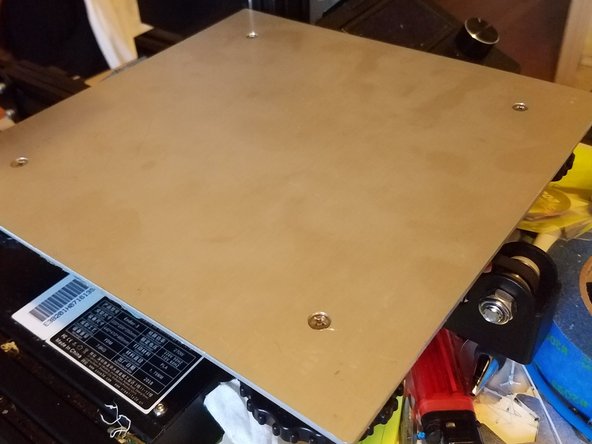
THIS IS SECTION B
-
When re-installing the plate, remember to get all of the screws through the gantry before you start tightening down adjustment wheels. Otherwise, you’ll end up with screws poking up into the print bed.
-
Otherwise, the previous few steps are universally applicable
-
-
-
BOTH SECTIONS END HERE
-
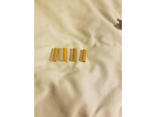
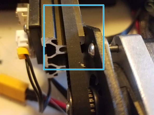
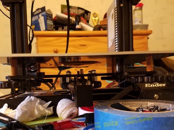
Due to the new bed springs being longer when compressed, I found it necessary to shift the Z end stop up by a couple millimeters. Not doing this caused my nozzle to dig into the bed.
-
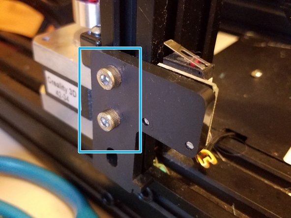
To do this, auto home the printer as if to level it, then move the gantry up about 4 millimeters, loosen the two screws on the side, and fiddle the end stop upwards until it clicks. Tighten it back down once you’re done.
-
Note: You may need to repeat this steps a couple times so that the endstop is high enough that you can do all of the normal leveling actions.
-
-
-
Congratulations! You have now finished section 2
-
-
-
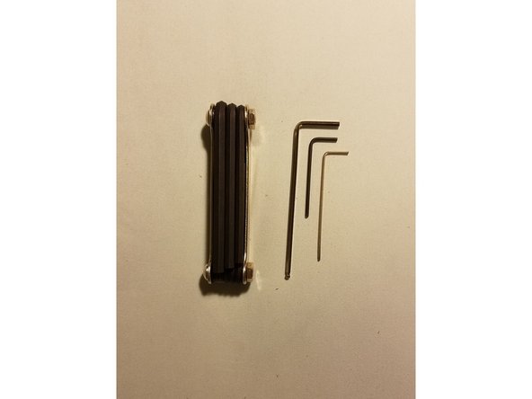
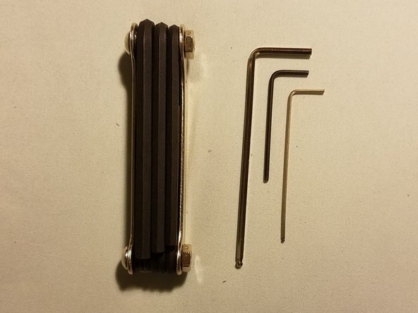
For this section, you'll need:
-
One of the larger Allen keys: in my case, that meant getting the multitool out
-
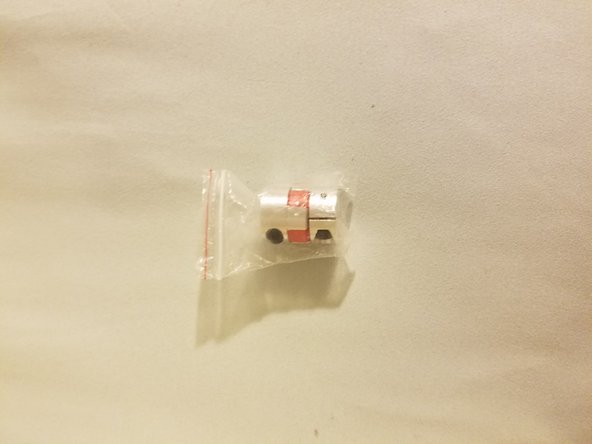
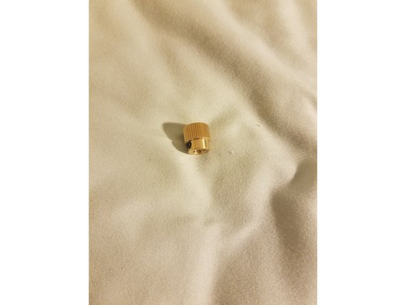
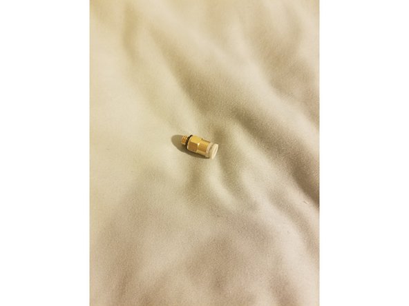
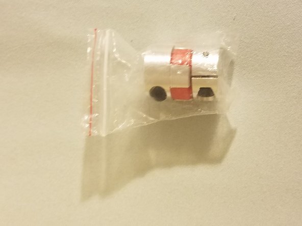
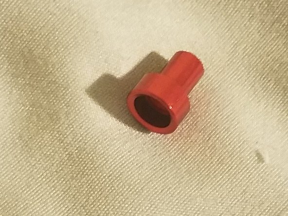
The lead screw adaptor
-
-
-
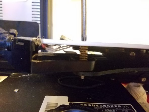
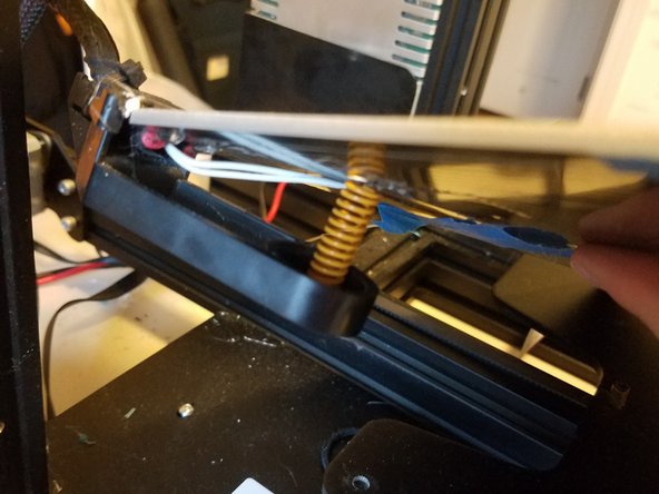
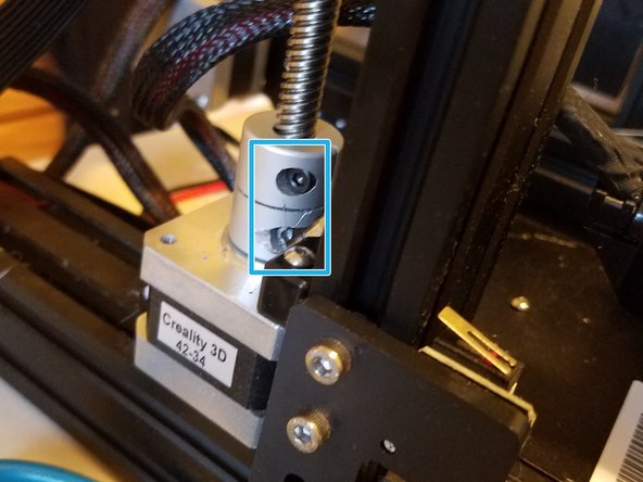
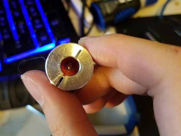
Loosen the two screws on the stock adaptor, then simply pull up on the lead screw, causing the piece to separate from either the printer itself, or the screw.
-
Remove the adaptor from the machine entirely and just let the screw sit on the motor shaft for now
-
-
-
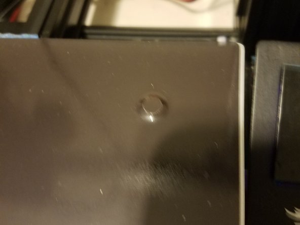
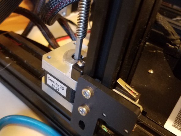
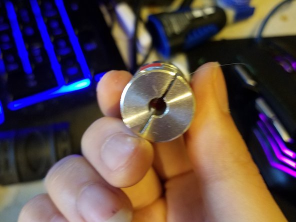
The new adaptor has a large hole end and and a smaller end.
-
Loosen both screws on it, and slot the smaller end over the motor shaft with the lead screw running into the larger hole.
-
Tighten both screws.
-
-
-
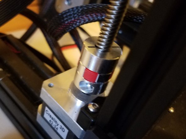
This section was only one upgrade part, but it should allow your printer to avoid damage if for some reason the nozzle was forcefully jammed down on a hard object like a print.
-
Either way, congratulations on completing it!
-
I forgot to take a thumbs up pic for this section
-
-
-
For this section you’ll need:
-
Three of your Allen keys, and the next 4 slides’ worth of parts
-
-
-
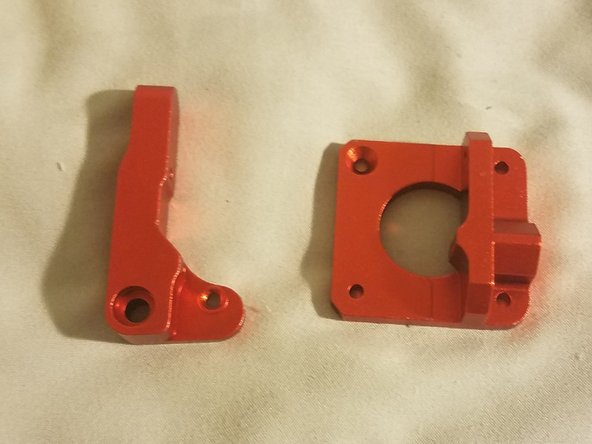
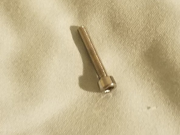
Parts needed:
-
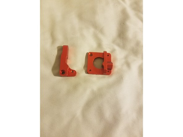
Extruder base and idler arm
-
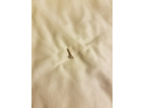
Idler hinge Screw
-
Idler arm bearing
-
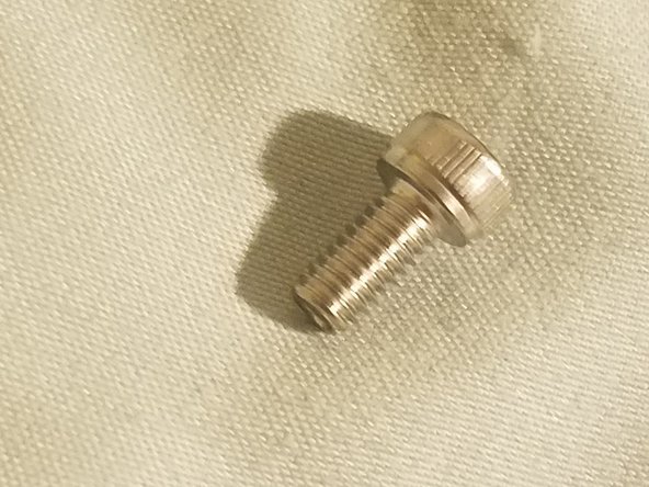
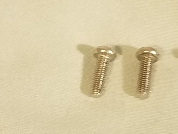
You'll also need one of your countersunk screws, the ones with the flat top and triangular silhouette
-
-
-
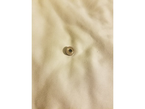
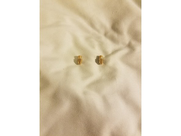
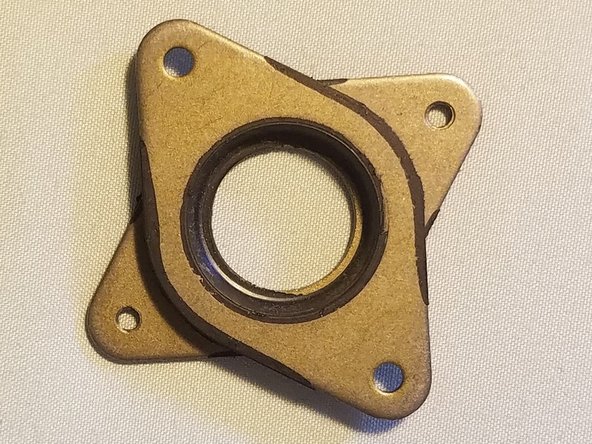
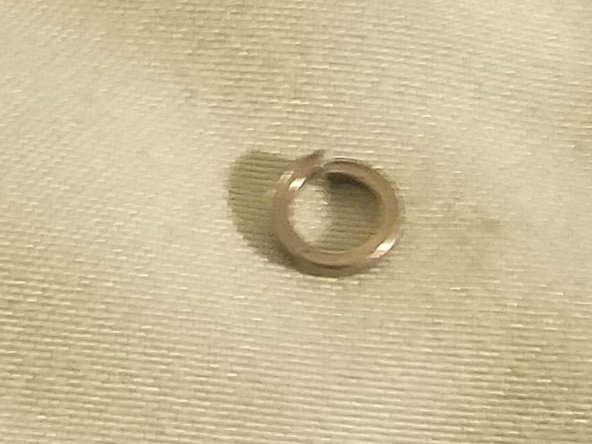
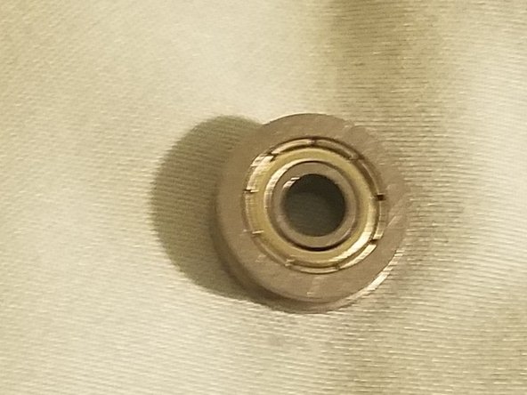
Parts needed:
-
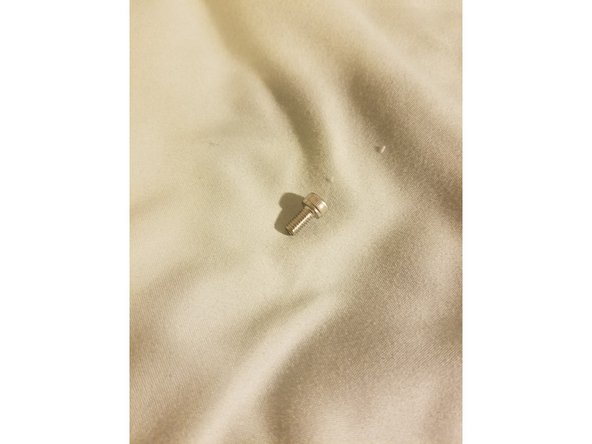
Filament bearing screw
-
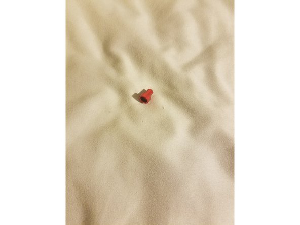
Filament bearing shim
-
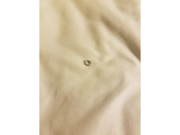
Filament bearing
-
-
-
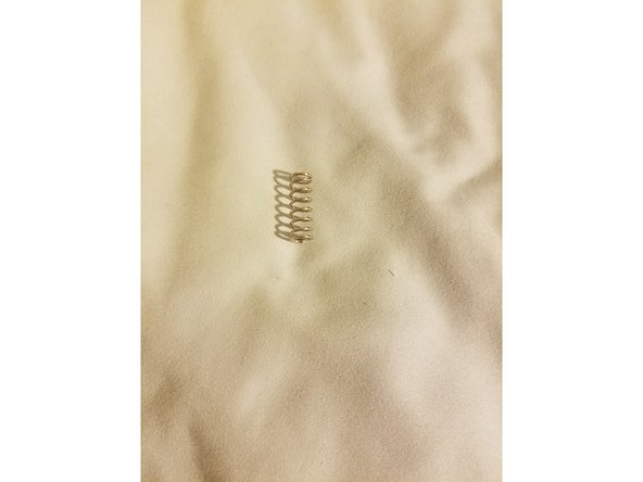
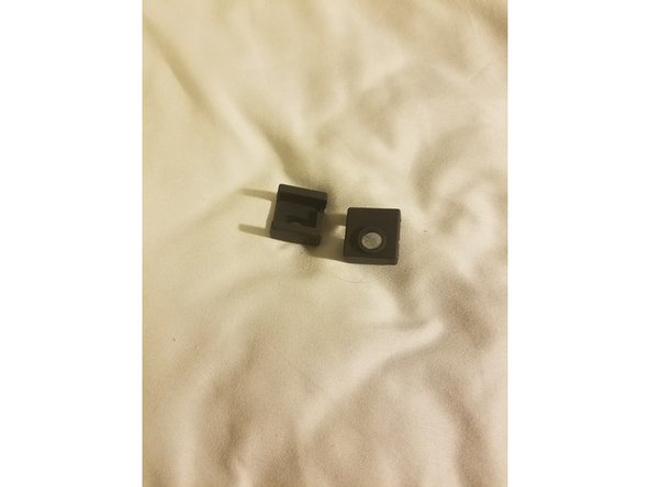
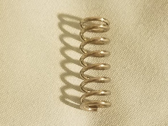
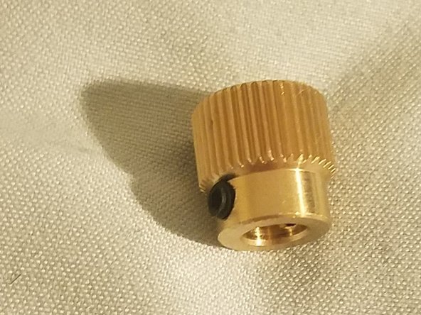
Parts needed:
-
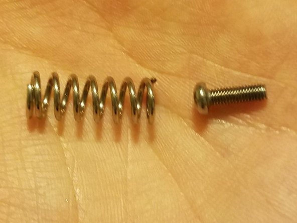
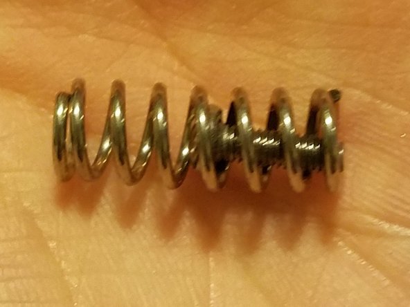
Idler arm spring
-
Filament drive gear
-
2 of your hex screws from earlier
-
-
-
I recommend laying everything out in roughly its correct placement.
-
Plus, this section requires the assembly of a couple small bits before you can actually put it on the printer.
-
-
-
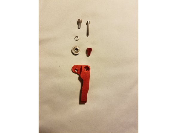
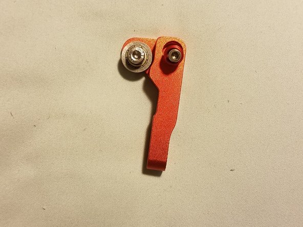
We’ll start with the idler arm and its components.
-
Arrange the following parts as shown and listed:
-
Filament bearing screw, filament bearing shim, and filament bearing on the left
-
Idler hinge screw and arm bearing on the right
-
-
-
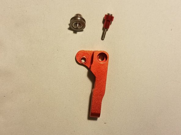
Put each screw through their respective parts as shown in these and the previous image, then place them into the arm.
-
Note: The filament bearing screw will need to be screwed in, but the Idler hinge screw can just sit loosely for now
-
-
-
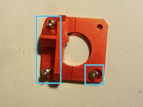
Stage everything together for convenience.
-
Your two hex rounded hex screws should be on the bowden side of the frame, with your countersunk screw going in the bottom right corner.
-
The Idler arm hinge screw fits through the top right corner
-
You’ll note that the idler arm spring is still loose, and will be held in place with screws taken from the printer itself.
-
-
-
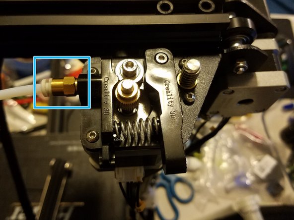
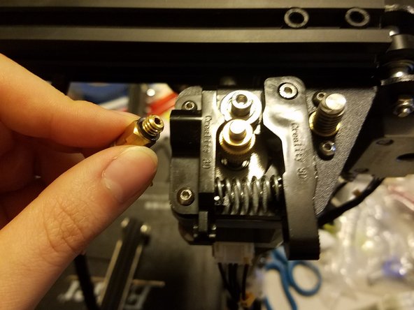
Start by pulling the gantry to the top of its travel.
-
Removing the bowden coupling. (You should be able to just unscrew it by hand)
-
-
-
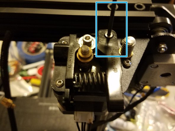
Note: The idler arm is under spring tension and will fly off to Narnia if you don't hold it in place
-
Undo and remove the idler arm screw while holding it in place.
-
Once the screw is gone, slowly remove the arm up and out, making sure not to let the spring fly off into oblivion
-
-
-
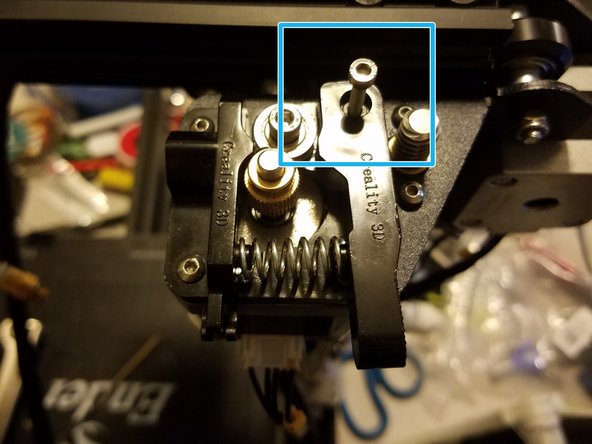
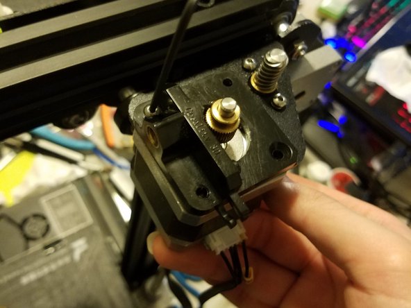
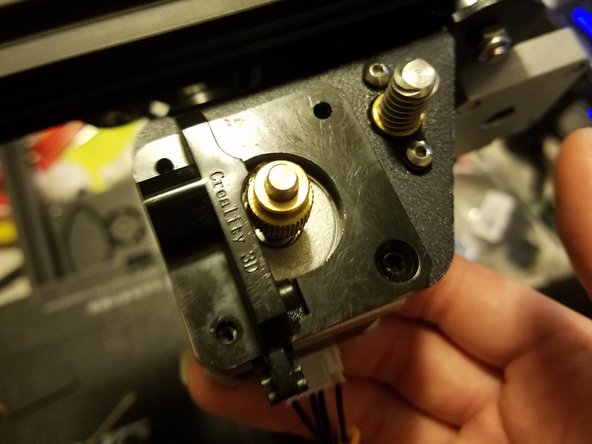
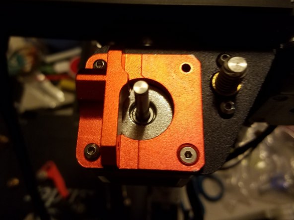
Note: The Extruder motor is held up by three screws and nothing else: Removing these screws will cause your motor to fall to the table
-
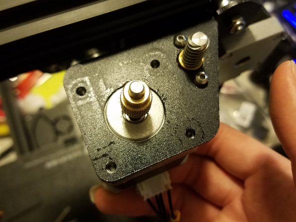
Holding the extruder motor in place, undo the three remaining screws securing the frame in place.
-
Once that’s done, you can just remove the frame and the motor
-
-
-
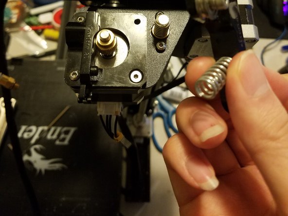
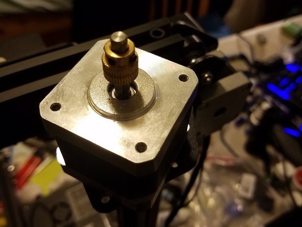
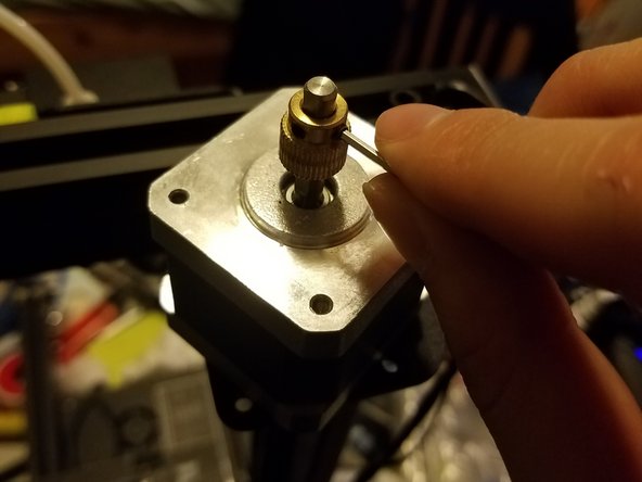
With the motor out, loosen the two grub screws holding the drive gear in place, and remove it.
-
-
-
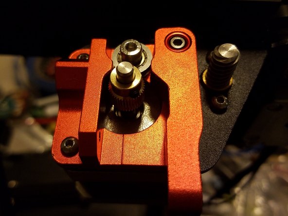
Place the motor and its frame against each other, then tighten the screws through the frame and into the four attachment points on the motor.
-
The first three screws can be tightened down, but the idler hinge screw should be just tight enough to move but not tight enough to inhibit the idler’s ease of motion.
-
-
-
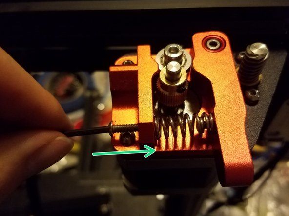
Place the filament drive screw onto the shaft, and hold it high enough so that the teeth and the bearing are at about the same height.
-
Tighten the two grub screws.
-
Note: The motor shaft has a flattened section that one of the grub screws should be tightened into and against, thereby helping to keep the gear from rotating on the shaft
-
-
-
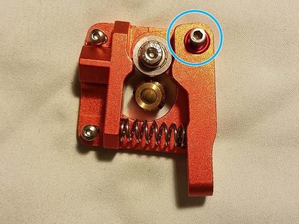
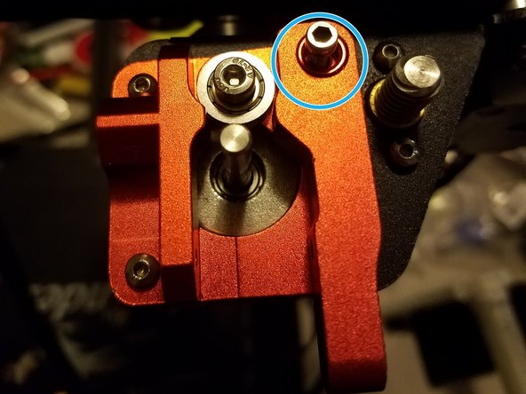
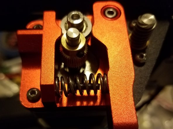
Place one of the hex screws you removed from the stock motor frame inside of the new spring, then compress it and slide it into position between the idler arm and frame.
-
-
-
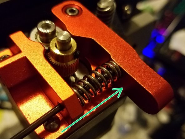
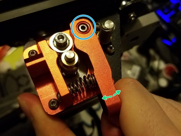
Place your allen key through the outside screw hole to tighten down the first hex screw into the idler arm.
-
Then take another rounded hex screw from the stock frame and tighten it into the outside hole.
-
Lastly, test the mechanism by squeezing it a couple times. The arm should swing smoothly along its screw and bounce back into place. If it’s stiff, loosen the hinge screw. If the arm has space to flop up and down, tighten the hinge screw.
-
-
-
With that last step done, you’ve completed the first of three Extrusion upgrades for the Ender 3
-
-
-
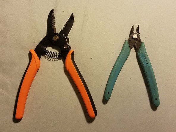
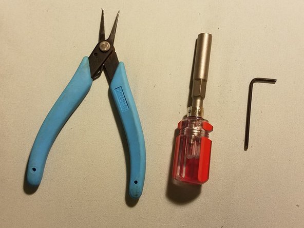
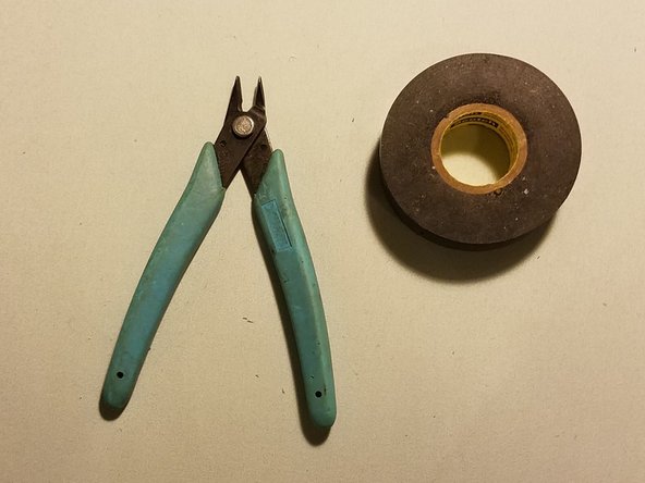
Tools and materials needed:
-
A wire stripper with gripping surfaces, and a flush cutter (If possible, switch these a flat metal wrench and a sharp knife, but I had neither of those so this is what I used)
-
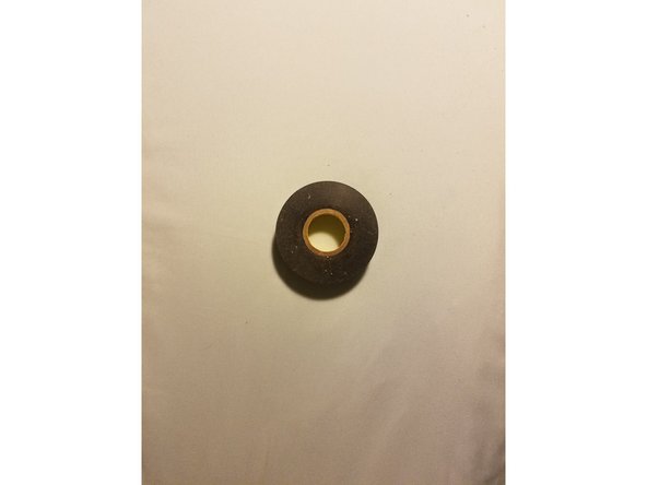
Electrical tape (Zip ties work too)
-
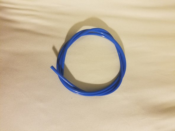
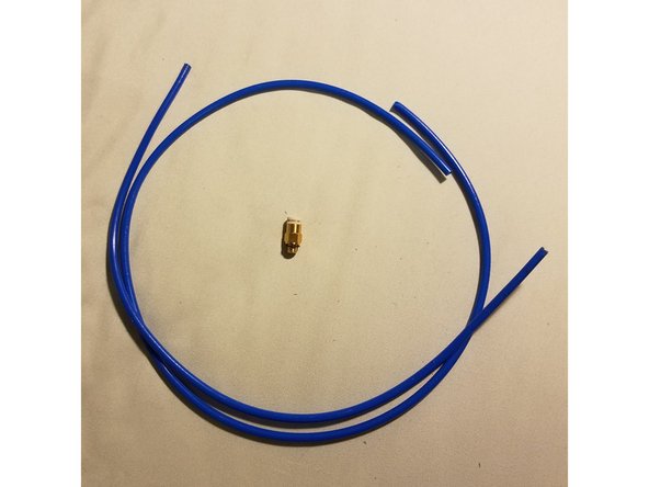
The new bowden tube and coupling
-
-
-
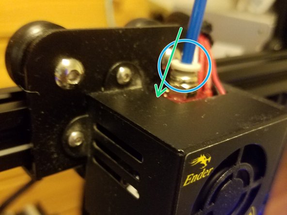
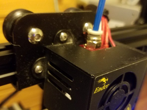
Safety note: While doing this, hold onto the fan housing and not the gantry arm to avoid burning yourself
-
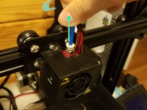
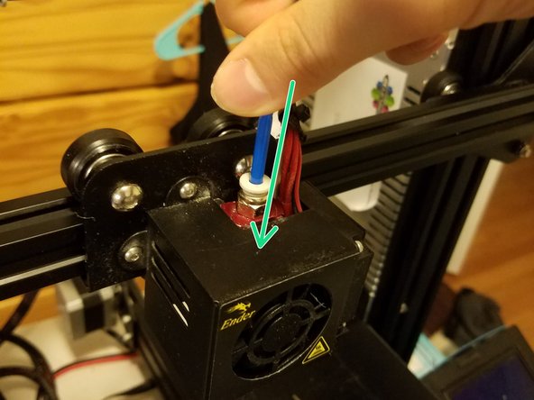
Turn on the printer and heat it to about 210 C, push the plastic ring at the top of the hotend coupling down, and pull the bowden out.
-
Operational note: My coupling was old and worn in, so I had to unscrew it with the wire strippers and pull the coupling out before separating the two pieces.
-
-
-
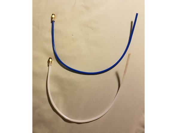
Connect the coupling to the tube by just inserting the bowden into the little plastic ring. That ring should be compressed towards the brass section and accept the tube. Both parts should now be stuck together without any space for the bowden to move in and out.
-
Then measure out the length you want the bowden to be at, about the same as the stock bowden, and carefully cut it to as flat as possible.
-
-
-
Fit the new bowden into the coupling while the hotend is still being heated.
-
Make sure that it goes in as far as it will go, since air gaps between the bowden and the nozzle will cause issues.
-
-
-
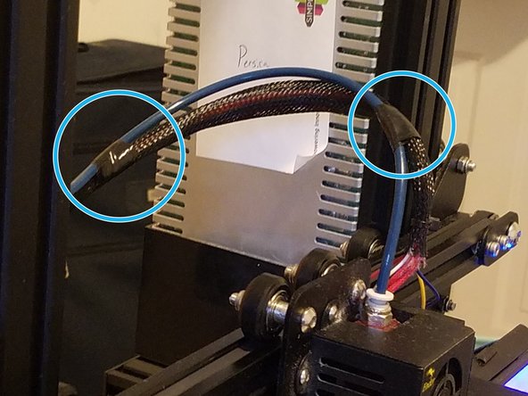
Use Electrical tape or zip ties to secure the wiring for the hot end electronics to the bowden tube so the both are angled together and neatly out of the way of the print bed.
-
-
-
You have now completed the second of three extrusion upgrades. Congratulations.
-
Don’t turn your printer off yet, this next upgrade needs a heated nozzle.
-
-
-
A screwdriver with a 6mm hex socket adapter, a pair of pliers, and one of your Allen keys
-
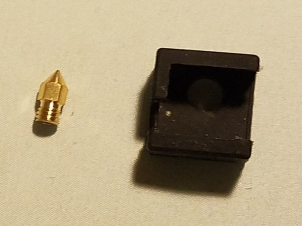
A nozzle (optional)and heat sock from your upgrade kit
-
-
-
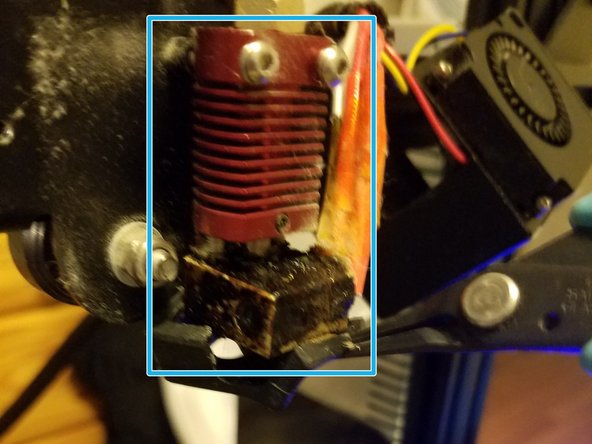
SAFETY NOTE: Do not touch any part of the vertical extrusion column. You will burn yourself
-
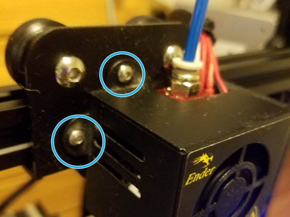
Undo the two hex bolts holding the fan housing, then swing it out and to the right to reveal the extrusion column
-
-
-
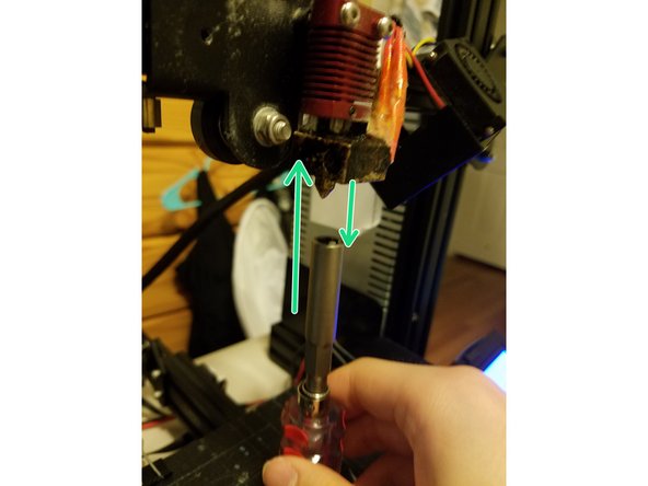
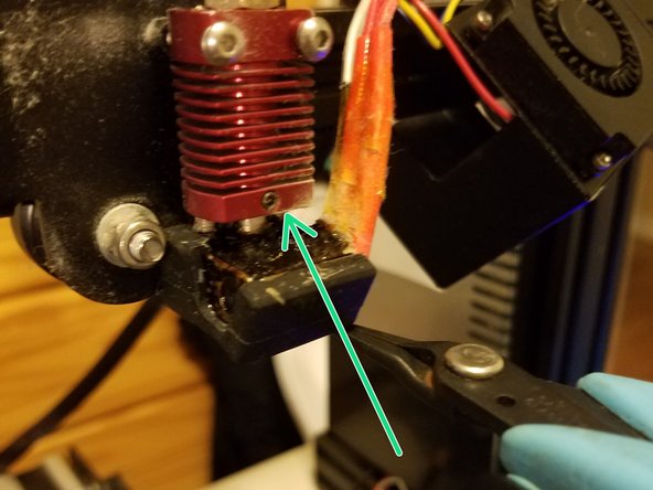
SAFETY NOTE: The nozzle is more than hot enough to boil water, don't let it touch you
-
Use the hex screwdriver to unscrew the nozzle
-
Note: Mine came out inside of the screwdriver, but yours may just fall out if you use different tools, so be cognizant that it’s still hot and don’t try to catch it as it falls
-
Using your pliers, place the new nozzle into the heat block, tightening it just enough that it doesn’t fall out, then tighten it the rest of the way using the screwdriver.
-
-
-
Using your pliers, gently place the heat sock over the heater block, then nudge it into place.
-
The big rectangular cut should face to the right in order to make space for the thermistor and heater cartridge wires.
-
Even with the cut, my heat socks were just weirdly shaped enough to not fit perfectly, and one end kinda dangles a bit. As long as it doesn’t go past the nozzle, it should be fine
-
-
-
Keeping away from the extrusion column, swing the fan housing back into place, and re-affix the hex screws in place.
-
-
-
With that done, you have finished the three upgrades to the Ender 3’s extrusion process. Congratulations
-
-
-
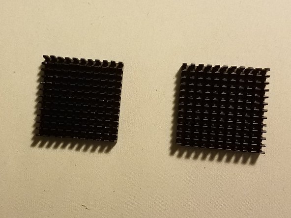
Tools and materials needed:
-
Electrical tape and something to cut it with
-
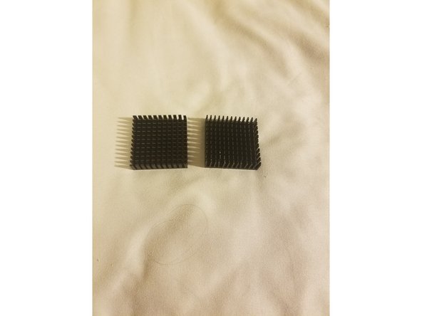
Both heat sinks
-
-
-
I’ll be honest, it was kind of weird for the makes of this kit to just send smooth backed heat sinks without any mounting solutions.
-
Because of this, I opted to just tape them to the two stepper motors with space behind them, those being the extruder motor and the X Axis motor.
-
-
-
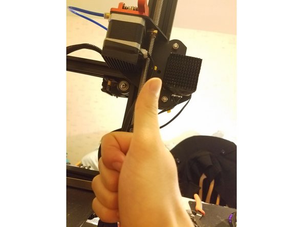
Well that was simple, congratulations on finishing the last step
-
-
-
And with that, your upgrade process is complete! (For now, who knows what else you’ll be inclined to slap on your printer)
-
If you have any questions, feel free to stick a comment down at the bottom.
-
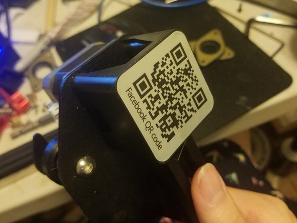
Hey look we’re back to doing thumbs up pics
-


Cancel: I did not complete this guide.
One other person completed this guide.