Difficulty
Moderate
Steps
7
Time Required
00:20:00
- How to Servo 360 7 steps

In Progress
This guide is currently being written. Reload periodically to see the latest changes.
Quiz
0
Tools
No tools specified.
-
-
Gather all of your parts required for this first step. We will assemble this servo's hardware first, then move on to software aspect. Each item in the parts section is necessary to create a working servo.
-
-
-
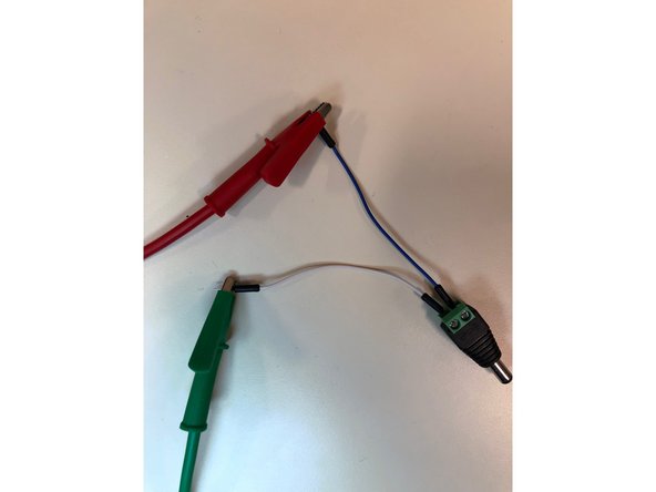
Before starting assembly, make sure the jumper wires you plan on using operate properly.
-
Put the multimeter into the continuity mode, which looks like the picture. Also, you need to click the select button once after turning the knob to that setting. You will be able to tell when the solid arrow with a line changes to an open circle and pulses.
-
Then, press one of the prongs onto each side of the wire. If it beeps, that means a signal can travel through and the wire works properly. If no sound is made, get another wire. Keep doing this step until all five jumper wires work properly.
-
-
-
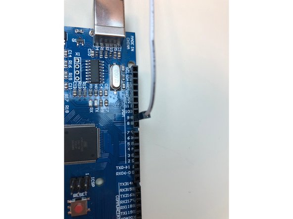
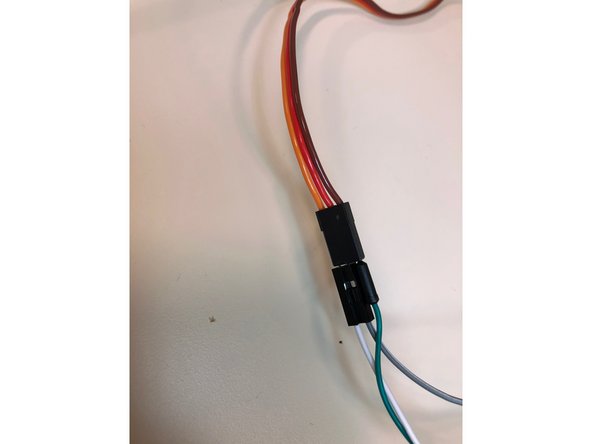
Attach a jumper wire(the thinner one with two pointed ends) from digital pin 9 to the orange colored female pin from the servo. Then, attach a male to male j. wire from the red wiring of the servo to the alligator clip from the positive end of the bench power supply and a male to male j. wire from the brown wire on the servo to the negative end.
-
-
-
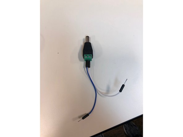
Put a male to male jumper wire into each end of the DC barrel plug, and then attach the j. wire from the positive end, denoted with a positive sign, to the positive alligator clip from the bench power supply and the negative j. wire to the negative alligator clip.
-
-
-
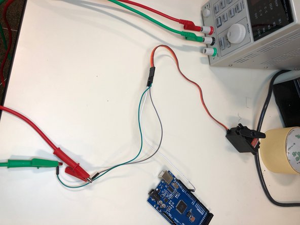
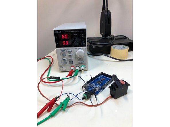
There should be two male to male jumper wires in each alligator clip, in the positive one, a j. wire from the red wire on the servo and also the positive end of the DC barrel plug. The negative alligator clip should have two m. to m. j. wires too, from the black servo wire and negative end of DC barrel plug.
-
Last j. wire is from digital pin 9 to the orange wire on the servo. After you're done, it should look like the picture where everything is assembled together.
-
-
-
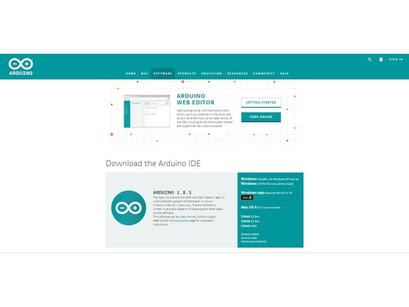
Make sure you install Arduino because it is how the servo will communicate with the Arduino. If you don't have it downloaded and don't know how to, here is a guide that will teach you how.
-
-
-
-
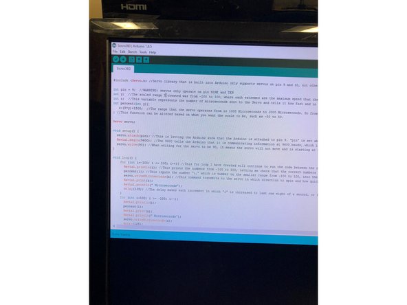
Here's some sample code for the servo: https://github.com/j-lam17/Servo360.
-
Use this code to experiment with the part and create code of your own.
-