Difficulty
Difficult
Steps
7
Time Required
01:00:00
- How to Control a Vibrator 7 steps

In Progress
This guide is currently being written. Reload periodically to see the latest changes.
Quiz
0
Tools
No tools specified.
-
-
Before starting assembly, make sure the jumper wires you plan on using operate properly.
-
Put the multimeter into the continuity mode, which looks like the picture. Also, you need to click the select button once after turning the knob to that setting. You will be able to tell when the solid arrow with a line changes to an open circle and pulses.
-
Then, press one of the prongs onto each side of the wire. If it beeps, that means a signal can travel through and the wire works properly. If no sound is made, get another wire. Keep doing this step until all five jumper wires work properly.
-
-
-
The first thing that needs to be addressed is the vibrator. The wires it comes with aren't compatible with any breadboard and will be useless unless we change something. Leads of solid wire need to be attached to the vibrators leads.
-
The addition of these leads is done by soldering solid core wire to the wires coming off of the vibrator. The amount of solid core wire is based on what your needs are, because the length doesn't affect how the vibrator will operate.
-
After that, heat shrink a case around the two recently soldered wires to protect them. This can be achieved by placing a casing over the wires, and applying heat from a heat gun until the casing shrinks around the wiring.
-
This change will make the vibrator easier to connect with the breadboard. The red lead on the vibrator is the positive side where power should flow into, and the black/blue wire is the negative end, where power should flow back to the Ground.
-
-
-
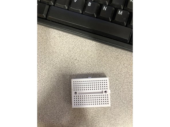
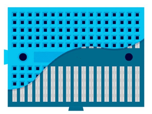
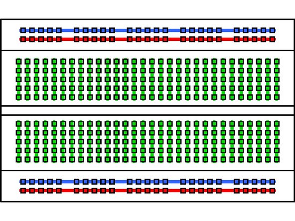
Breadboards are arranged like in the picture. Note the connections like demonstrated in the picture. They are organized in columns when it is set up long ways horizontally, and don't cross over the gap in between.
-
The larger looking breadboard is an actual breadboard that comes with a power line for positive and negative leads. The difference between a mini breadboard and a normal one is the number of columns and the power line.
-
-
-
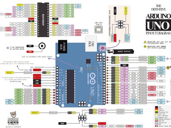
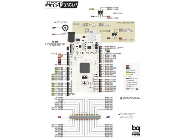
Take the Arduino and plug in a male to male jumper wire in a PWM supported digital pin. A PWM pin means that the Arduino can output information beside s a 1 or 0, or a yes/ no. This means that there can be a type of granularity with the outputted information.
-
For an UNO, it is pins : 3,5,6,9-11
-
For a Mega 2560, it is pins : 2-13
-
-
-
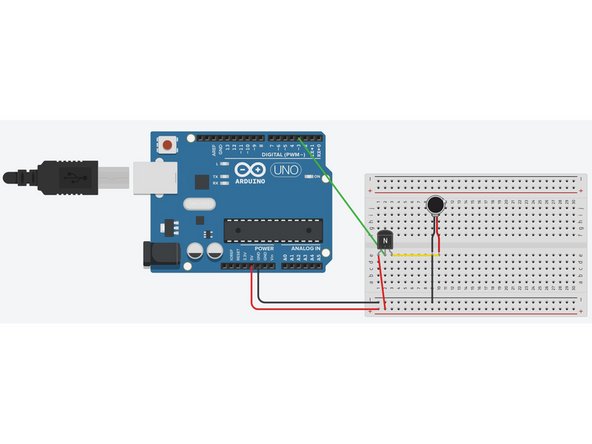
Take a male to male jumper(j.) wire and attach it to a digital pin with PWM capabilities. Put the other end of that j. wire to column in the breadboard. In this column of the breadboard, the transistor's base pin will go here too.
-
Secondly, take another male to male j. wire and plug it into the 5V power pin on the Arduino. This j. wire will lead to a separate column from the digital pin and transistor's base, attaching to the collector of the transistor.
-
-
-
Attach the vibrator's positive end, the red wire from the vibrator, to the emitter pin of the transistor. This is achieved by putting both wires into the same column.
-
Attach the black/blue wiring of the vibrator to another column, and have that go to the ground of the arduino via a j. wire.
-
-
-
-
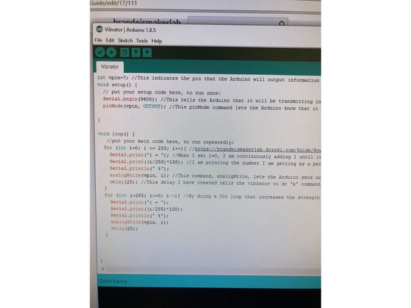
The link above will lead you to the sample code created to demonstrate how to operate a vibrator.
-
The code is commented to make it easier to understand what each command's purpose is. Open the code and modify it to learn how to make your own code and have it do something else like turn off and on in certain intervals.
-