Difficulty
Moderate
Steps
19
Time Required
168:00:00
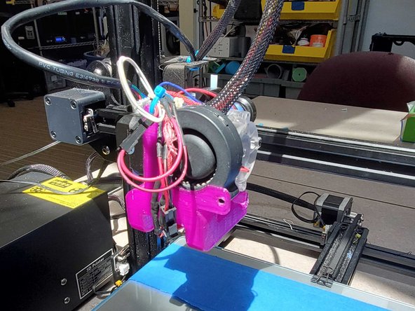
- Creality CR-10 with E3D Titan Aero 19 steps

User-Contributed Guide
This guide is not managed by the site's staff.
Quiz
0
Introduction
This documentation is meant to cover the lab’s Creality CR-10 printers with E3D Titan Aero upgrade kits installed and doesn’t cover Enders or the Hemera extrusion kit
-
-
REMEMBER TO KEEP THE RETRACTION DISTANCE BELOW 2MM OTHERWISE IT WILL INEVITABLY JAM
-
The CR-10 will work with both rigid and flexible materials
-
When working with rigid filaments, loosen the idler almost all the way back
-
When working with flexible material, tighten the idler until the arm can only be pulled back a couple mm by hand
-
This is because the titan aero extruder package has a very well policed filament path, so a looser idler may allow filaments to flex out of alignment or slip against the extruder gear
-
When printing with a glass plate, try to aim for consistent extrusion that flattens out and does not lift from the bed. If there is inconsistent bubbling, your nozzle is probably too close to the bed
-
-
-
Heat the nozzle and remove any filament in the printer
-
Undo and remove the two screws holding the heat sink fan to the heat sink
-
Undo and remove the four smaller screws on the heat sink behind the fan
-
Make sure to hold the part fan bracket when undoing the corresponding screws
-
When reassembling, make sure not to overtighten the top right screw, and the two screws holding the fan bracket on
-
Pull the heat sink out to the right to disassemble it
-
-
-
-
Most likely to be 0.4mm in diameter, but may vary, so check for labels on top of the frame to make sure
-
Incompatible with stock CR-10 or ender nozzles due to length, make sure to use the special V6 ones
-
-
The heater cartridge is crimped into the block via a single hex screw
-
-
Keeps the heat block warm and helps maintain consistency in nozzle temperature when printing
-
-
-
-
Unlikely to need changing, unless it starts sparking
-
Needs to be cut and resoldered
-
-
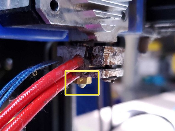
Held into the heat block by a single grub screw
-
Can be simply unplugged and replaced, but rarely needs to be
-
-
-
-
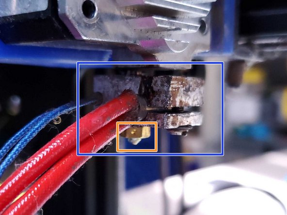
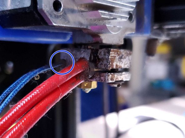
Connects the heat block to the heat sink
-
Can be rather finicky, make sure to not overtorque either the heat block or the nozzle or it could shear off, leaving both parts unusable without a difficult removal
-
Try to make sure there is thermal paste on the threads between it and the heartbreak and the heatsink.
-
-
-
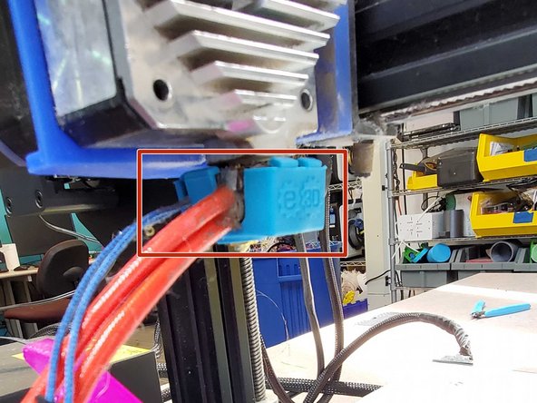
Heat the nozzle up to normal print temperatures
-
Remove any filament in the printer
-
Remove heat sock by pulling down with a pair of pliers
-
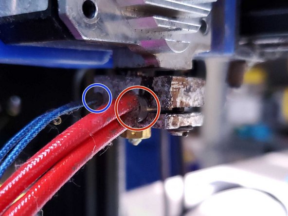
The nozzle itself uses clockwise threading, so it can simply be unscrewed to be replaced
-
Make sure the new nozzle is threaded tightly and does not leave a gap between itself and the heatbreak, doing so will cause print quality issues and eventual jamming
-
-
-
Unplug the printer
-
Cut the thermistor cords a good distance above the insulation strips
-
Heat the heat block up using a soldering iron
-
Unscrew and remove the hex screw
-
While holding the heat sink, alternate between gently prying the gap open and pushing on the blunt end of the cartridge until it loosens
-
Taking care not to burn yourself, push the cartridge all the way through and then resolder a new cartridge
-
-
-
Heat the block either using the cartridge or a soldering iron
-
Loosen the grub screw holding the thermistor in place until it can be poked out from the other side
-
Replace thermistor and tighten the grub screw just enough to hold it in place, but not enough to crush the glass bead inside
-
-
-
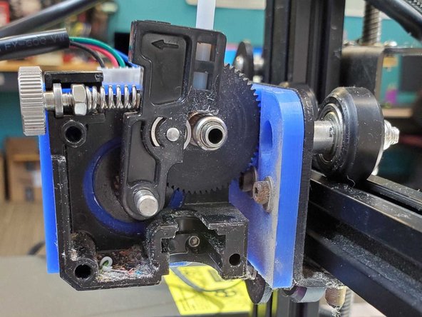
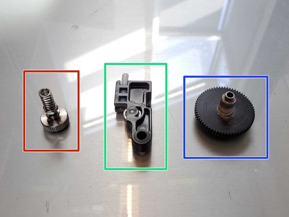
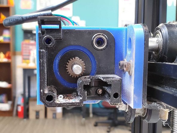
Idler bar
-
Holds a PTFE tube and guides filament in from outside of the printer
-
Holds a wheel against the filament to keep tension on the filament
-
Idler knob, nut, and spring
-
Keep tension on the idler bar
-
Adjustable tension for different materials or other needs; rigid filaments need a looser idler, flexible filaments need a very tight idler
-
Extruder gear
-
Transfers motor movement into filament movement
-
-
-
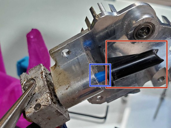
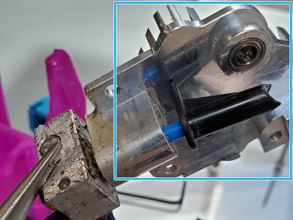
Filament cone(?) thing
-
Contains a length of PTFE tube to help guide the filament down
-
Guides filament from between the idler bar and extruder gear into the heat sink and nozzle
-
Second image is the chassis with all parts removed from inside
-
-
-
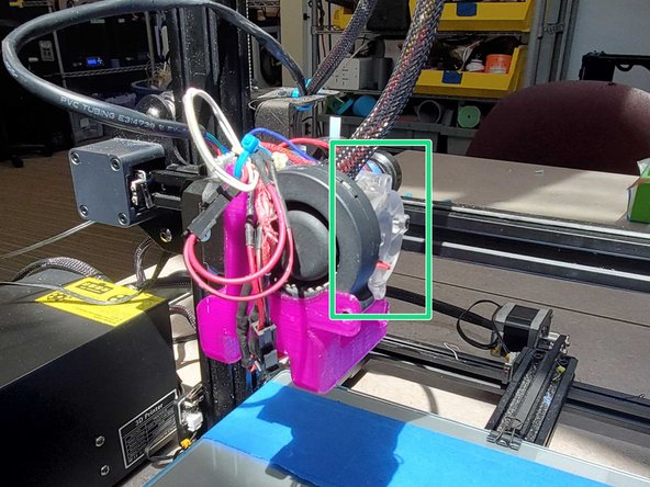
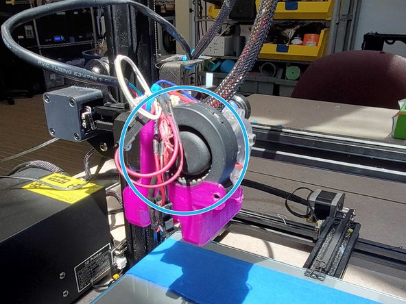
Heat Sink Cooling Fan
-
Prevents heat creep in the heat break and upper components
-
Heat Creep is a phenomenon in which heat travels too far up the filament path, melting too much plastic and causing friction that will eventually jam the printer
-
-
Holds the heated parts to the extruder package and dissipates excess heat
-
-
-
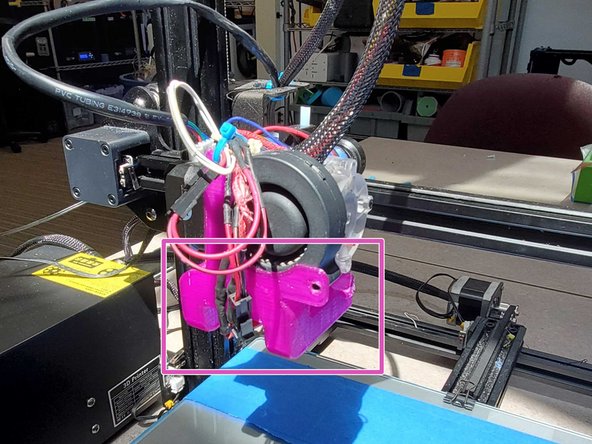
Part Cooling Fan
-
Cools extruded filament at the nozzle to improve print quality
-
-
Holds the cooling fan
-
-
-
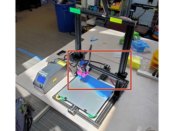
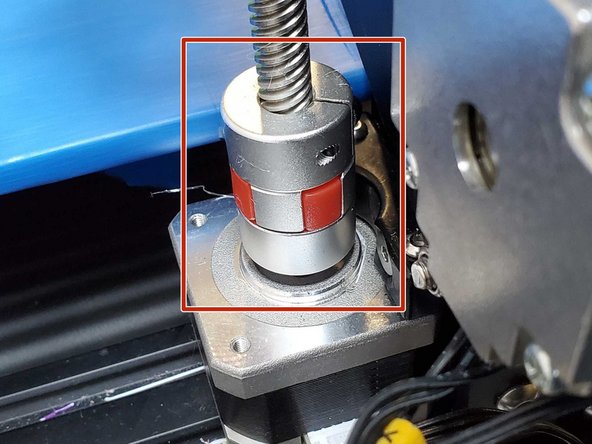
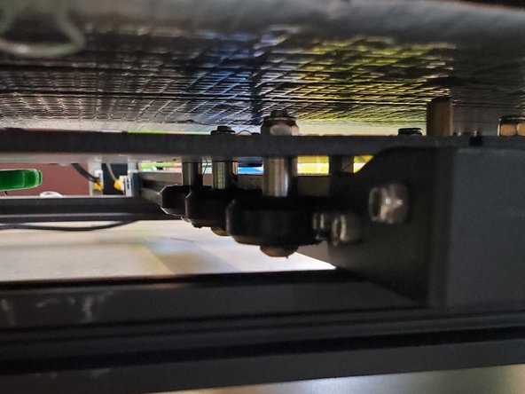
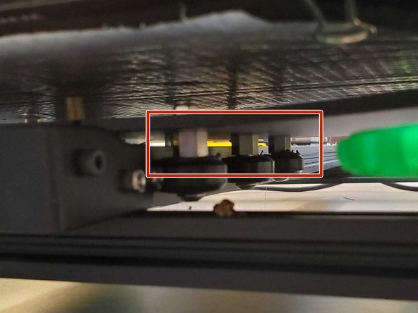
This horizontal bar allows the nozzle to move along the X axis, and is suspended by a lead screw on the left side of the frame
-
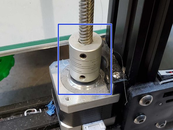
The lead screw comes with a fixed adaptor cylinder on the motor which simply transfers motor movement to screw movement
-
Some of our printers have an upgraded adaptor, which can detach with enough upwards force in the event a faulty GCODE forces the nozzle downward in a way that would otherwise stress and damage the printer
-
-
-
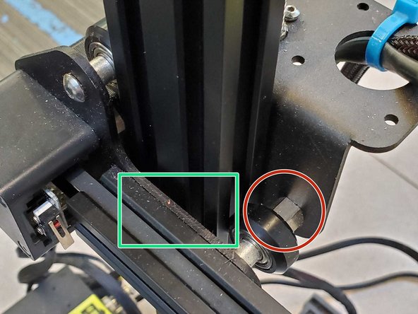
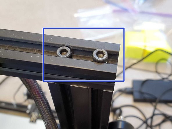
The Gantry's tightness to the frame should ideally be just enough that movement is as free as possible without any play between it and the frame
-
Tightness can be adjusted using the eccentric nuts marked in red, there is also one on the underside of the moving carriage that adjusts its tightness to the gantry. That one should be as loose as possible without there being any play between the carriage and gantry
-
The gantry is secured to the wheel frames on either side by two hex screws each that are hidden when it is in place
-
These screws can only be accessed by removing the gantry altogether, steps for this are on the next page
-
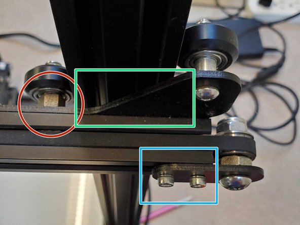
X Axis belt tension can be adjusted by loosening the two marked hex screws and pulling out on the pulley frame before retightening.
-
Pry the pulley out against the frame with a thicker Allen Key or screwdriver to the desired belt tension
-
Tighten the innermost screw so that the frame rotates freely
-
Rotate the pulley frame to be parallel with the gantry so that the belt moves freely, then tighten the other hex screw
-
-
-
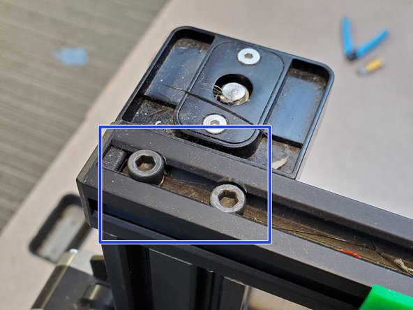
Undo the four large hex screws at the top of the frame and remove the top bar
-
If you have a lead screw adaptor loosen one of its grub screws until either the screw separates or the motor does
-
If you have an upgraded adaptor you can just pull straight up to separate it from the frame
-
Pull up on the X Gantry until it clears the printer frame and separates completely
-
Make sure not to pull too far or else you risk damaging the wiring
-
-
-
The Print bed is attacked to the printer frame in much the same way as the extruder carriage, but with six symmetrically distributed wheels instead of three unevenly distributed ones
-
The right side wheels all come with eccentric hex nuts like the X Gantry, adjust accordingly
-
-
-
Disassembly
-
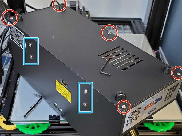
Unplug the printer before beginning
-
Remove the five hex screws holding the bottom cover on
-
The power supply unit is fixed to the frame by the four larger hex screws.
-
Make sure to hold the psu when undoing the screws and be careful to not damage the wiring when you set it aside
-
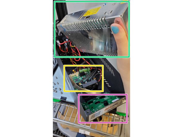
Power supply unit
-
Motherboard
-
Display board
-
-
-
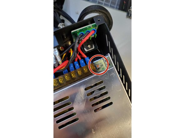
The makerlab can be a chilly, drafty place during the winter, and sometimes the bed voltage needs to be increased in order to make sure it heats and doesn't give a thermal runaway or heating failure
-
The PSU does not need to be removed from the frame in order to make this adjustment
-
Simply rotate the phillips head adjustment screw clockwise until it stops turning
-
-
-
Sometimes one of the stepper motors will stutter back and forth for no apparent reason
-
If there is nothing obstructing its movement and you have tried plugging the wire into a different motor which also begins to stutter, it is probably a motherboard driver issue
-
The motor driver cannot be replaced and thus the entire motherboard needs to be swapped out to fix the issue
-