Difficulty
Moderate
Steps
8
Time Required
24:00:00 - 72:00:00
- Build a Desk Extension 8 steps

In Progress
This guide is currently being written. Reload periodically to see the latest changes.

User-Contributed Guide
This guide is not managed by the site's staff.
Quiz
0
Introduction
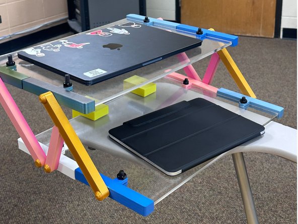
Students have complained about the lack of desk space in some classrooms. We wanted to make an extension unit for the desks to provide more room for students to maneuver.
Therefore, we provided a place where they could put their laptops in front of them and write at the same time.
-
-
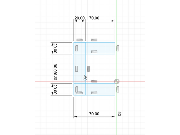
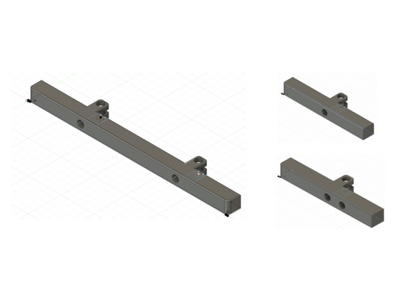
Create a sketch. The sketch should consist of three rectangles. For the two horizontal rectangles, make the width 20 mm and length 70 mm and for the one vertical rectangle, the width is the same and the length is 90mm.
-
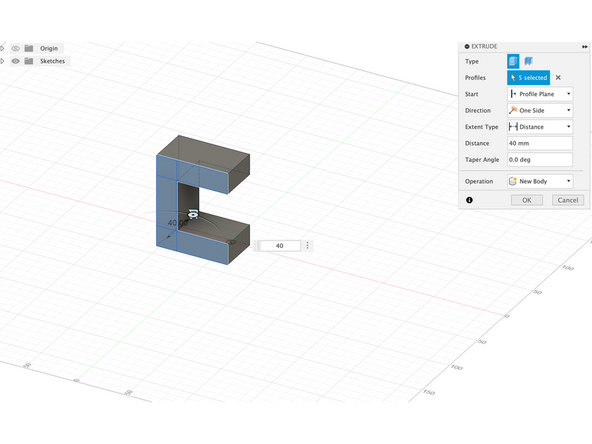
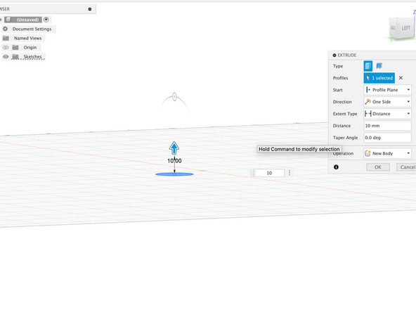
Extrude the entire sketch to 40mm.
-
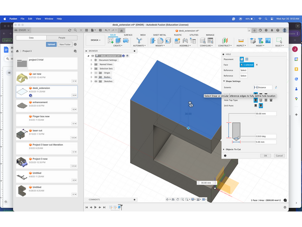
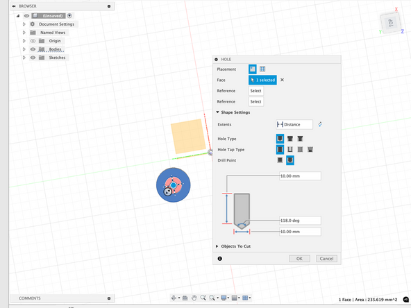
Using the hole function, make a 5mm hole on the top of the shape, drilling all the way through. Then make another hole on the bottom of the shape drilling 15mm in.
-
-
-
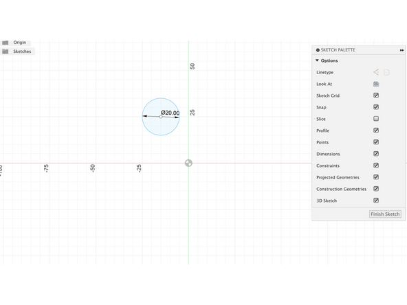
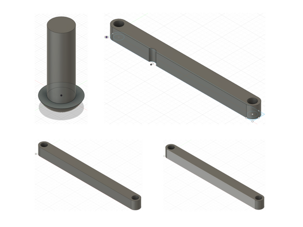
After finishing the design of the clamp, make another sketch of a 20mm circle.
-
Extrude this circle 10mm.
-
Add a hole using the hole function that is 10mm deep.
-
-
-
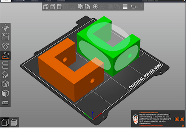
Export the file as an .stl file and import the file into prusa slicer. Once in Prusa Slicer make a copy of the clamp and use the place on face function to lie both the claps on the side.
-
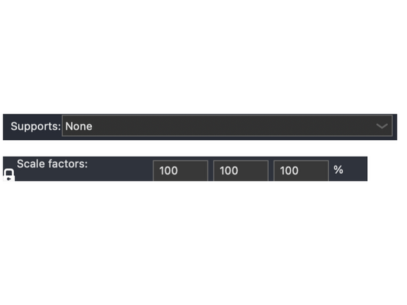
Make sure there are no added supports to the clamps to speed up the printing process. The clamps should be left at 100 scale.
-
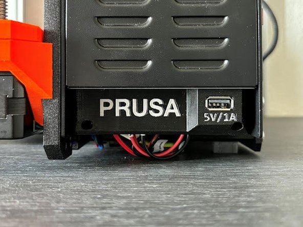
Export the STL file onto the USB, and make sure to extract the file before taking out the USB. Plug the USB into the Prusa Mini printer and begin the printing process.
-
-
-
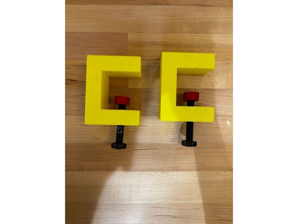
Screw in the bolt into the hole of the clamp.
-
Screw the tab onto the other side of the screw.
-
repeat this process for the second clamp.
-
-
-
Measure the computer and some other objects that may be placed on the tabletop, perform possible force analyses to obtain lengths of support rods that provide optimal load-bearing structures.
-
-
-
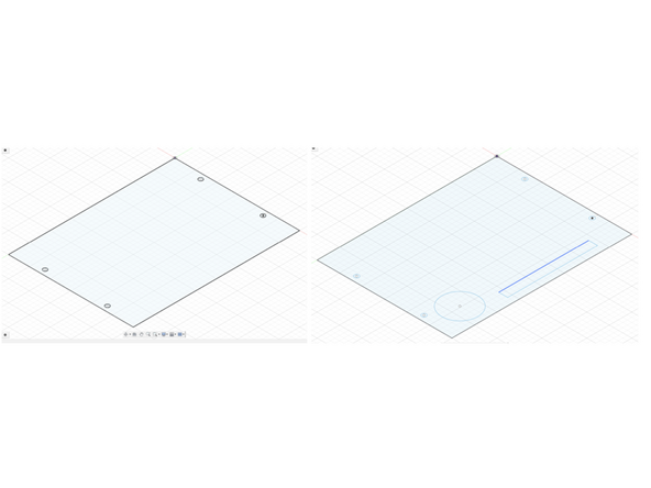
Sketch the table board in fusion as a rectangle and an additional sketch with cup and pen slots for the top table board, with four holes pre-drilled in the sketch for the bolt holes
-
Draw a part that will wrap up and secure the edges of the two acrylic boards (in order to ensure the strength of a table board is composed of two layers of acrylic boards), in addition, in addition to the outside of the pre-drilled holes needed to install the support rods
-
Drawing of support rods and screws
-
-
-
The table board will be imported into Light Burn for cutting, the other files are saved as stl files with prusa slicer for slicing and adding the necessary support and export bgcode for printing.
-
Due to the limitations of the printer, the acrylic board on both sides of the fixing strips are divided into two parts of the print (of course, so that can not be avoided to affect the load-bearing capacity and stability)
-
-
-
Assemble the printed and cut out parts, paying attention to the position of the different support rods when assembling, use metal bolts and nuts to fix the acrylic plate and the fixing strips on both sides
-
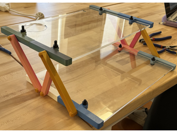
The desk board section acts as an extension of the desk, the clamp and arm sections help to secure the desk board to the desk or wheelchair.
The desk board section acts as an extension of the desk, the clamp and arm sections help to secure the desk board to the desk or wheelchair.